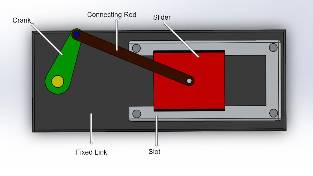
Theory
A slider crank mechanism is a four link mechanism. It has three revolute joints and one prismatic or sliding joint. This mechanism is used to change rotatory motion to linear motion and vice versa. It contains a crank which rotates about a fixed axis. Generally piston moves inside the cylinder and gives reciprocating motion. The piston and crank are connected through a connected rod which transmits the motion from crank to piston and vice versa.
Types of slider crank motion mechanism
1) In line : An in-line slider-crank has its slider positioned so the line of travel of the hinged joint of the slider passes through the base joint of the crank. This creates a symmetric slider movement back and forth as the crank rotates.
2) Off set : If the line of travel of the hinged joint of the slider does not pass through the base pivot of the crank, the slider movement is not symmetric. It moves faster in one direction than the other. This is called a quick-return mechanism.
Applications
1) IC engine : In IC engine the reciprocating motion of the piston inside the cylinder converted into rotary motion. Inside the cylinder combustion happens and the pressure and temperature of the combustion product increases. Due to this pressure and temperature rise the gas expands and pushes the cylinder, swiping out the volume. This motion is converted into rotary motion through connecting rod and crank-shaft arrangement.
2) Reciprocating Compressor : In reciprocating compressors the gas is compressed inside the cylinder using a piston. The piston is connected to the crank through a connecting rod. The crank is given input power through an external source. The rotatory motion is changed into the reciprocating motion.
In the reciprocating compressor the input is given to the crank while in the I C engine input is given to the piston.